How to Program an 8x8 Matrix with Arduino
45-60 min
14-18
What Will You Learn?
You will learn more about programming and electronics to control 64 LEDs, with the help of loops, arrays and creating your own functions.
Define Your Variable
Step 2
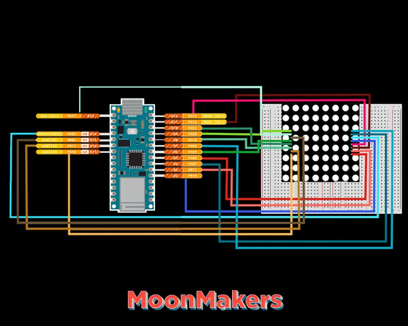
The matrix has columns and rows, like a Cartesian plane, to turn on the LEDs, you will access them with coordinates; Define the columns and rows at the beginning of the code, using #define as follows:
“
#define ROW_1 2
#define ROW_2 3
#define ROW_3 4
#define ROW_4 5
#define ROW_5 6
#define ROW_6 7
#define ROW_7 8
#define ROW_8 9
#define COL_1 10
#define COL_2 11
#define COL_3 12
#define COL_4 13
#define COL_5 A0
#define COL_6 A1
#define COL_7 A2
#define COL_8 A3
“
A tip: most arduinos have 13 digital pins, these allow you to send electricity and control outputs such as LEDs or motors. Although it has the pins that are Analogue, which allow the outputs and inputs, this means sensors of light, temperature, humidity, among others. You will use the Analog Pine for the missing columns (5 to 8)
Step 3
With your variables defined, you will create a variable to access your columns and lines, to work much easier, write the following:
“
const byte rows [] = {
ROW_1, ROW_2, ROW_3, ROW_4, ROW_5, ROW_6, ROW_7, ROW_8
};
const byte col [] = {
COL_1, COL_2, COL_3, COL_4, COL_5, COL_6, COL_7, COL_8
};
“
Step 4
Now place the coordinates of the LEDs that will turn on, start by turning on all of them, with the following code:
“
ALL byte [] = {B11111111, B11111111, B11111111, B11111111, B11111111, B11111111, B11111111, B11111111};
“
This variable called “ALL”, the B represents the line, and in front you have 1, this means that it will turn on you can write 0 to turn off, and each of these numbers represent the eight columns, completing your matrix.
Void Setup Section
Step 5
In the void setup section, we place our pins, we will use the loop for, copy and paste the following code:
“
for (byte i = 2; i <= 13; i ++) {
pinMode (i, OUTPUT);
}
pinMode (A0, OUTPUT);
pinMode (A1, OUTPUT);
pinMode (A2, OUTPUT);
pinMode (A3, OUTPUT);
“
The “for” helps you by placing pins 2 to 13 as OUTPUT, you create a loop that continues with all the pins marking them as output, when it ends, it continues with the analog pins marking them one by one.
Create a Function
Step 6
You are almost done with your code, now create a function, this is a part or fraction of code that is going to be executed, this will help you control the matrix of leds
“
void drawScreen (byte buffer2 [])
{
// Turn on each row in series
for (byte i = 0; i <8; i ++) // count next row
{
digitalWrite (rows [i], HIGH); // initiate whole row
for (byte a = 0; a <8; a ++) // count next row
{
// If the LEDs are backwards, put (buffer2 [i] >> a)
digitalWrite (col [a], (~ buffer2 [i] >> a) & 0x01); // initiate whole column
delayMicroseconds (100); // uncoment delay for different speed of display
// delayMicroseconds (1000);
// delay (10);
// delay (100);
digitalWrite (col [a], 1); // reset whole column
}
digitalWrite (rows [i], LOW); // reset whole row
// otherwise last row will intersect with next row
}
}
“
You wrote “void drawScreen” which declares and in parentheses the action you want it to do.
The function will help to show what you want, it has a For, which for each row will reset all the LEDs and activate the ones you need taking into account the columns.
Void Loop Section
Step 7
Once the function is finished, in the “void loop” section we will write the following code:
“
void loop () {
drawScreen (ALL);
}
“
Step 8
Verify, save and upload the code to your arduino, you will see how all the LEDs light up. This is because we are using the ALL in “void loop” where we made all the LEDs light up, you can change or add different variables of letters, numbers or figures.
What's Next?
Try Out Other Shapes
They can experiment with creating different shapes, letters, shapes, or even emojis. Use your creativity to create and experiment with what you have learned.
You can make a timer so that a letter appears, wait a while and another appears to be able to read a word or an animation appears.
Further Resources
Learn More!
About MoonMakers
MoonMakers — led by Camila and Diego Luna — are a community of creators passionate about knowledge. A Makerspace, an open space with different digital manufacturing machines. And a YouTube channel where we promote science, technology and the maker movement.
MoonMakers have collaborated with companies such as: Sesame Street, Make Community and in Mexico with Educational Television and Fundación Televisa, creating educational content.
We have given workshops throughout the Mexican Republic with: Talent Land, Secretary of Education in Jalisco, Conacyt, Centro Cultural España.

Materials:
- Arduino microcontroller (We will use the Arduino Nano 33 loT, but you can use the Arduino microcontroller of your choice)
- A matrix of 8x8 LEDs
- 18 cables
- Breadboard
- A micro usb cable
- A computer, with the Arduino IDE
Vocabulary:
function: is a section of a program that calculates a value independently from the rest of the program
void setup: The setup () function is called when a sketch begins. Use it to initialize variables, pin modes, start using libraries, etc. The setup () function will only run once, after every power-up or reboot of the Arduino board.
void loop: After creating a setup () function, which initializes and sets initial values, the loop () function does just what its name suggests and repeats consecutively, allowing your program to change and respond. Use it to actively control the Arduino board.
int: Integers are your main data type for storing numbers.
#define: It is a useful C ++ component that allows the programmer to name a constant value before compiling the program. The constants defined in arduino do not take up program memory space on the chip. The compiler will replace references to these constants with the value defined at compile time.
pinMode: Sets the specified pin to behave as an input or an output.
digitalWrite: Write a HIGH or LOW value to a digital pin. Its voltage will be set to the corresponding value: 5V (or 3.3V on 3.3V boards) for HIGH, 0V (ground) for LOW.
delay: Pauses the program for the time (in milliseconds) specified as a parameter. (There are 1000 milliseconds in a second.)
MoonMakers
Maker Camp Project Standards
Based on NGSS (Next Generation Science Standards)
NGSS HS.Engineering Design
The Next Generation Science Standards (NGSS) are K–12 science content standards.- HS-ETS1-1. Analyze a major global challenge to specify qualitative and quantitative criteria and constraints for solutions that account for societal needs and wants.
- HS-ETS1-2. Design a solution to a complex real-world problem by breaking it down into smaller, more manageable problems that can be solved through engineering.
- HS-ETS1-3. Evaluate a solution to a complex real-world problem based on prioritized criteria and trade-offs that account for a range of constraints, including cost, safety, reliability, and aesthetics as well as possible social, cultural, and environmental impacts.
- HS-ETS1-4. Use a computer simulation to model the impact of proposed solutions to a complex real-world problem with numerous criteria and constraints on interactions within and between systems relevant to the problem.


